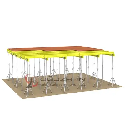
GENERAL FEATURES OF TELESCOPIC STRUCTURING SYSTEM:
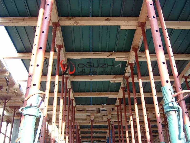
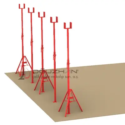
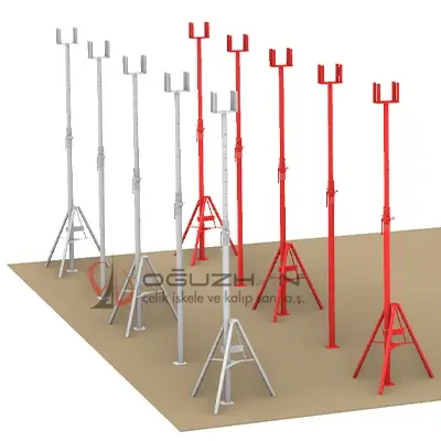
What is Telescopic Prop? Telescopic Strut System is also known as "Iron Pole System". It is one of the most used systems among the under-form scaffolding systems. It can be easily used in many reinforced concrete structures such as underfloor formwork systems, under-beam formwork systems, and engineering structures.
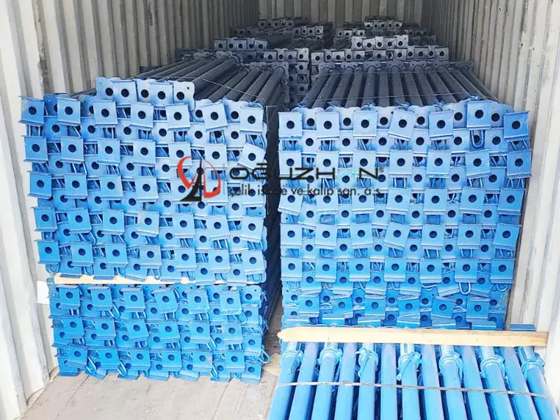
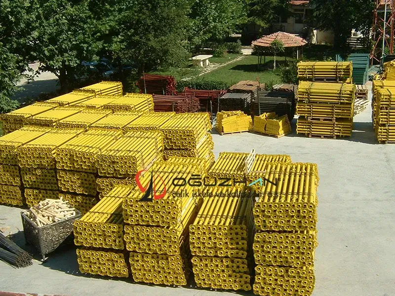
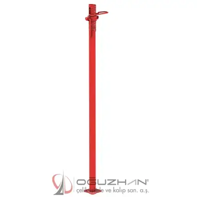
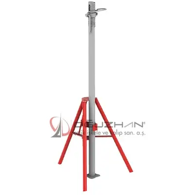
Props ; It consists of 6.0mm base plate, 60.0/2.5mm 1 outer tube, 1 48.0/3.0mm inner tube, 60.0/3.0mm fine adjustment screw and fine adjustment nut welded to the outer tube. Head parts are fixed to the inner pipe part by welding.
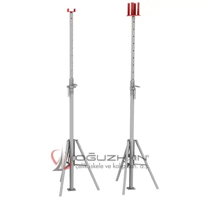
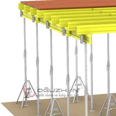
The head part changes according to the working conditions and preference. There are 4 types of headers: Flat Head, U Head, Beam Head (T Head) and Four Way Head.
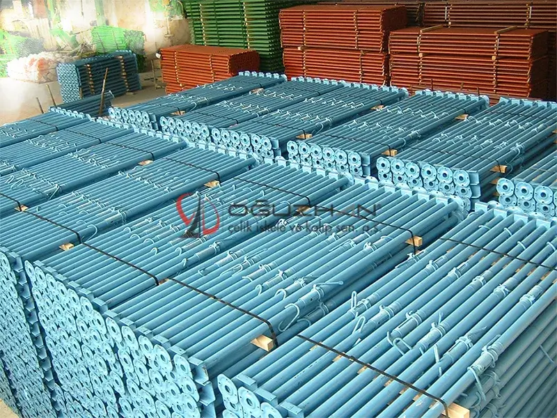
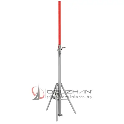
Telescopic Props ; The inner pipes, which have holes at certain intervals, can be opened and closed in the outer pipe, 1.75 mt.-6,00 mt. It can be adjusted practically according to any working height between It is a system that is easy to use as individual elements, has a wide working area, and is resistant to continuous use.
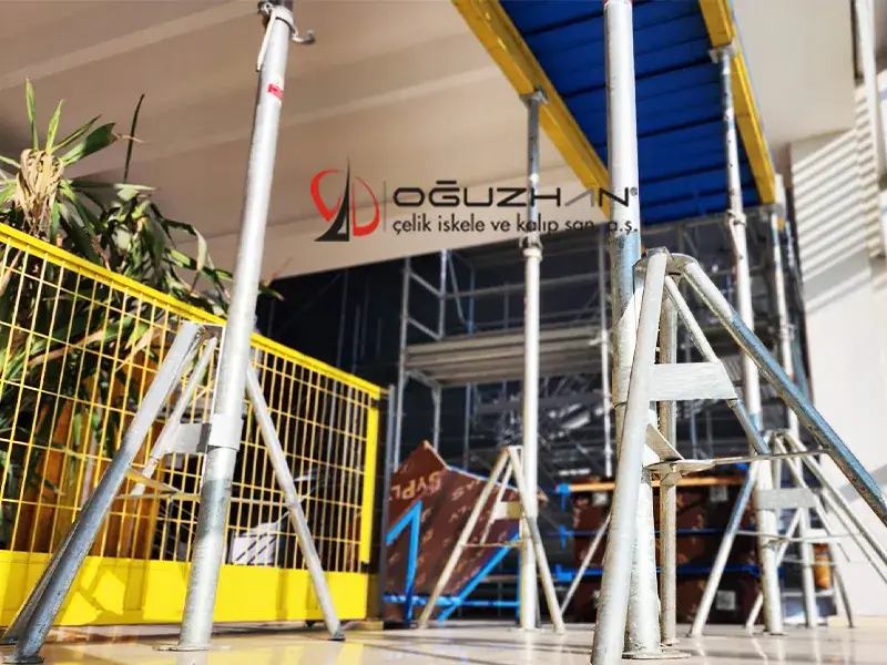
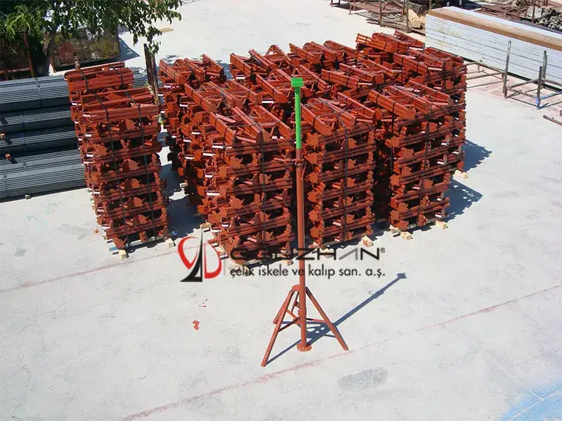
Tripod (three legs) stand elements are used in cases where the working distance is high and there is a risk of tipping. The tripod is connected to the telescopic pole from the outer pipe and provides a safe upright system.
Telescopic Scaffolding Materials are produced under the brand name of OĞUZHAN® in accordance with TSE EN ISO 3834-2 Quality Conditions Standard for Melting Welding of Metallic Materials.
The pipes used in the production of telescopic poles are manufactured from pipes that have undergone mechanical and chemical tests and comply with TSE EN 10219-2 Structural Steel Pipe Standard.
Telescopic Strut System; It consists of Base Plate, Telescopic Outer Tube, Telescopic Inner Tube, Fine Adjustment Screw, Fine Adjustment Nut, Adjustment Hook, Head Systems, Tripod Stand (Tripod) and Accessories.
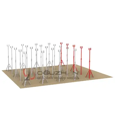
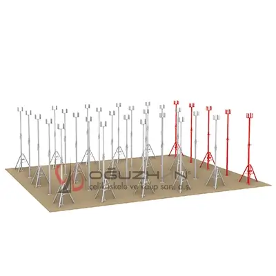
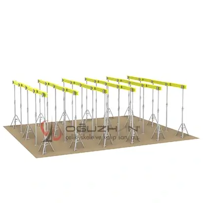
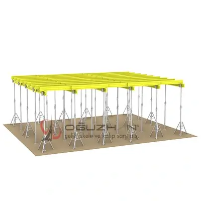
Installation: The ground on which the scaffolding system will be installed is made ready for installation, Telescopic Props are selected according to the height of the formwork, Telescopic poles are prepared for installation at certain intervals in accordance with the carrying capacity and safety, Inner pipe part is opened according to the required height, Final adjustments are made with the fine adjustment nut and hook. and the telescopic pole system is fixed, tripod stands are added from the outer pipe parts for the safety of the system against overturning, the system is completed by placing wooden materials and flooring materials under the formwork.
Telescopic Outer Pipe: It is the outer pipe element of the telescopic pole system. Outer pipes are manufactured from 60.0/2.50mm steel pipes as standard. It can also be manufactured according to different wall thicknesses. Their lengths can be 150cm, 200cm, 250cm and 300cm depending on the telescope size. They are joined by welding with a fine adjustment screw made of 60.0/3.0mm steel pipes, they work as a single material in structure. The base plate made of 6mm sheet metal with an area of at least 15cm2 is also welded to the lower part of the outer pipe.
Telescopic Inner Pipe: It is the inner pipe element required for the telescopic strut system to be adjusted to different heights. It is manufactured from 48.0/3.0mm steel pipes as standard. It can also be manufactured according to different wall thicknesses. Their lengths can be 150cm, 200cm, 250cm and 300cm depending on the telescope size. In order to adjust the height of the telescopic pole, there are rough adjustment holes with a diameter of 15mm on the inner tube through which hooks are inserted at certain intervals. The inner pipes are used by welding together with the head part from their upper parts.
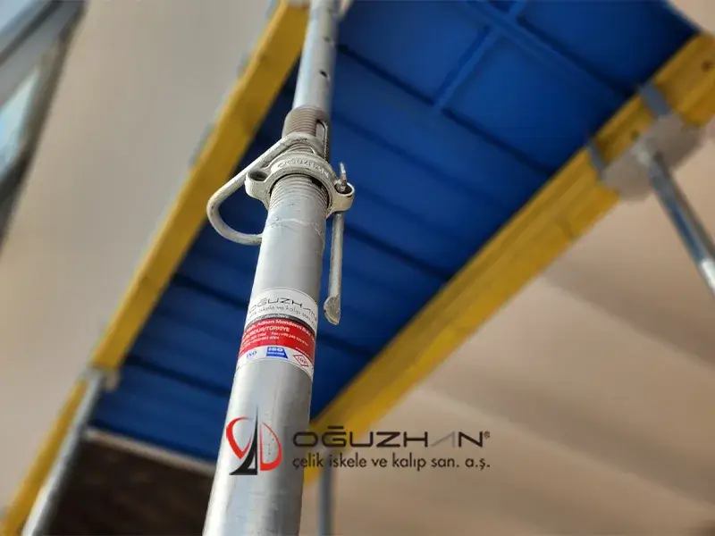
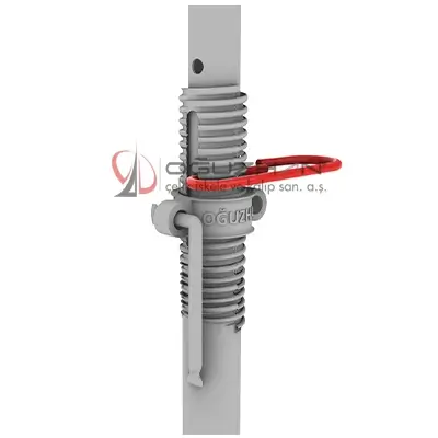
Fine Adjustment Screw: It is the element that contains the adjustment mechanism in the telescopic strut system. It is manufactured from 60.0/3.0mm steel pipes as standard. Its height is 25cm. Threads are made for the mechanism system on 60.0/3.0mm pipes. It is fixed by welding with a telescopic outer tube and combined with the mechanism with a fine adjustment nut. Fine Adjustment Nut moves up and down on this mechanism.
Fine Adjustment Nut and Hook: These are the elements that ensure the safety of the connection between the inner and outer pipes in the telescopic strut system. While adjusting the height of the telescopic pole, the hook is inserted into the holes on the inner tube, and this connection is fixed with the fine adjustment mechanism and nut. Adjusting Nut and Hook are both effective in the stability and safety of the system.
Heading Systems: Heading systems are attached to the ends of the inner pipes by welding. It is the top element of the system. Head types vary according to under-mold working conditions and material preference. There are 4 types of headers: Flat Head, U Head, Beam Head (T Head) and Four Way Head. There are no adjustable shaft parts like the upper adjustment shaft used in other under-form scaffolds. In the telescopic system, they are used only as a head on the upper part of the inner tube. In this system, the adjustable part is not the head, but the inner tube part.
Four-Way Head Fastener: Before the assembly of the formwork flooring elements, the Main Carrier H20s and the Secondary Carrier H20s are placed on top of each other. The Four-Way Head Attachment also allows the Head System and Main Carrier H20s to be fixed to each other.
Beam Connecting Bracket: They provide the connection between the Main Carrier H20s placed between the headers before the formwork flooring elements are placed, and the Secondary Carrier H20s that are frequently placed under the floor. They increase the safety of the formwork system.
Accessories : These are the materials used to increase the functionality and safety of the scaffolding system. Connection Pipe, Fixed Clamp, Movable Clamp, Four Way Head Fastener, Beam Connecting Bracket, Plywood, Wooden Beam H20 etc.
annotation
Another name is ACRO JACKS.
Access (Facade) Scaffolding Systems ….…. | Shoring Scaffolding Systems …...… ……. |
| Ring-Lock Scaffolding | Table Type H Scaffolding |
| H Type Safety Facade Scaffolding | Tower Type Scaffolding |
| Italy Type - Safety Facade Scaffolding | Cup-lock Scaffolding |
| Mobile Scaffolding Tower | Shoring Telescopic Prop System |
Column and Wall Formwork Systems ……. | Safety Systems ……………… ….…………... |
| Single Side Formwork | Safety Barrier System (Edge Protection) |
| Steel Surface Formwork | Safety Net System |
| H20 Beam Formwork | Material Transfer Platform System |
Special Formwork Systems ……… …………. | Accessories ……….…..…… ….……..….…… |
| Steel Slab Board | Auxiliary Work Equipment |
| Patterned Garden wall Formworks |
